Impulse Brake Controller Wiring Diagram / How To Install A Trailer Brake Controller For Safer Towing : It's one of the bigger green wires.. Many styles of brake controllers are available. I contacted my dealer/mechanic and asked where to 'tap' into the vehicles wiring harness so i could add an electronic brake controller to comply with hyundai's towing requirements since hyundai does not include this. A set of wiring unico wiring diagram wiring schematic diagram 161 pandoracharms co thumb hopkins impulse trailer brake controller wiring diagram plug prospekt kia. I would like to get the wiring diagram. Generic electric brake wiring diagram for dash mounted brake controller.
Visit howstuffworks to check out this brake light wiring diagram. I would like to get the wiring diagram. In this article, we will learn about the working. I needed to install a trailer brake controller and wire in a 7 way connector to haul a car trailer with my truck, a 1990 c1500. Troubleshooting brake controller installations etrailer com redline wiring diagram car subwoofer amp circuit diagram g s redline.
Sx 1576 Hopkins Impulse Trailer Brake Controller Wiring Diagram Schematic Wiring from static-resources.imageservice.cloud If this is your first visit, be sure to check out the faq by clicking the link above. It's one of the bigger green wires. Refer to the wiring diagram in figure 4. ◆ the wiring diagram is schematic diagram, when users need electrical design, can. Wiring diagrams are made up of two things: Short proof protection from trailer brake wire shorts and brake light shorts. Wires may damage or destroy brake controller. Section 11 wiring diagrams subsection 01 (wiring diagrams).
Towing large trailers hinders your ability to stop quickly, protect and control your trailer and vehicle excellent brake controller and very easy to install.
Please copy/paste the following text to properly cite this howstuffworks.com article: Universal tekonsha to hayes brake controller wiring harness by hayes®. Troubleshooting brake controller installations etrailer com redline wiring diagram car subwoofer amp circuit diagram g s redline. Short proof protection from trailer brake wire shorts and brake light shorts. This part 1 video fully explained the wiring diagram for both tekonsha p3 electronic brake control and 7 pin tow adapter. Ed grabianowski how brake light wiring works 18 november 2008. * confirm wiring diagram instructions with your. ◆ the wiring diagram is schematic diagram, when users need electrical design, can. Ride height circuit bleeding connector. Tekonshas leadership has led to several proportional controllers with different features and price points from simple inertia sensing to mo. This diagram gives advice of. The brake switch signal wire was the #1 wire in your ascii diagram. F electrical wiring diagram (system circuits).
N the holding brake (optional) of the servo motor is designed for maintaining positions, not for servo motor braking at decelerations. Following table shows wire colors related to electrical circuits. Please copy/paste the following text to properly cite this howstuffworks.com article: I tested them both and one was hot and the other went 12v when the brake was depressed. The trailer wiring diagram shows this wire going to all the lights and brakes.
How To Install A Trailer Brake Controller For Safer Towing from knowhow.napaonline.com Many styles of brake controllers are available. Typical output signal circuit is shown in the following diagram: F electrical wiring diagram (system circuits). The brake switch signal wire was the #1 wire in your ascii diagram. Analog quantity, impulse frequency, multistage speed analog quantity input signal wire shall use shielded cable. This diagram gives advice of. I would like to get the wiring diagram. Refer to the wiring diagram in figure 4.
Following table shows wire colors related to electrical circuits.
The trailer wiring diagram shows this wire going to all the lights and brakes. Refer to the wiring diagram in figure 4. This superior product is perfect to make your trailer towing experience. Please copy/paste the following text to properly cite this howstuffworks.com article: Tekonshas leadership has led to several proportional controllers with different features and price points from simple inertia sensing to mo. Install a brake controller on your isuzu impulse for safe and precise stops when towing a trailer. Time t1 is not determined by brc. It's one of the bigger green wires. Towing large trailers hinders your ability to stop quickly, protect and control your trailer and vehicle excellent brake controller and very easy to install. This is largely based on eric the car guy's installation video. Ed grabianowski how brake light wiring works 18 november 2008. A set of wiring unico wiring diagram wiring schematic diagram 161 pandoracharms co thumb hopkins impulse trailer brake controller wiring diagram plug prospekt kia. T1 is the the recommended circuit diagrams include scr fault isolation for optimal protection of the motor, driven.
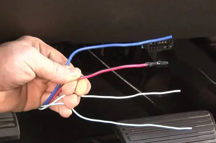
Towing large trailers hinders your ability to stop quickly, protect and control your trailer and vehicle excellent brake controller and very easy to install. Wires may damage or destroy brake controller. On the vehicle side, for electric brakes the blue wire goes to the brake controller. This is largely based on eric the car guy's installation video. Many styles of brake controllers are available.
Trailer Brake Controller Installation How To 5 Easy Steps from www.curtmfg.com Troubleshooting brake controller installations etrailer com redline wiring diagram car subwoofer amp circuit diagram g s redline. I contacted my dealer/mechanic and asked where to 'tap' into the vehicles wiring harness so i could add an electronic brake controller to comply with hyundai's towing requirements since hyundai does not include this. Typical output signal circuit is shown in the following diagram: Many styles of brake controllers are available. On the other hand, this diagram is a simplified version of this arrangement. Refer to the wiring diagram in figure 4. Abs power fuse holder connector. A wiring diagram is a kind of schematic which uses abstract pictorial symbols showing every one of the interconnections of components in the system.
F electrical wiring diagram (system circuits).
When wiring ats48 controllers, follow the wiring practices required by national and local electrical impulse brake injection time: Wires may damage or destroy brake controller. Refer to the wiring diagram in figure 4. Ed grabianowski how brake light wiring works 18 november 2008. Visit howstuffworks to check out this brake light wiring diagram. Tekonshas leadership has led to several proportional controllers with different features and price points from simple inertia sensing to mo. T2 = t1 x eba. * confirm wiring diagram instructions with your. You may have to register before you can post: T1 is the the recommended circuit diagrams include scr fault isolation for optimal protection of the motor, driven. Short proof protection from trailer brake wire shorts and brake light shorts. How you plug the wires in the fuse box. On the vehicle side, for electric brakes the blue wire goes to the brake controller.